Milling
- Yurii Kotsun
- Oct 31, 2023
- 4 min read
Updated: Nov 5, 2023

Milling is a widely used process in mechanical machining in which a rotating tool, the milling cutter, is used to remove material from a workpiece and create a desired shape or surface structure generate. During milling, the tool is moved either in a rotating motion around its own axis of rotation or along a specified path while the workpiece is fixed. The milling tool, also called a milling cutter, consists of a large number of cutting edges or cutting teeth that are arranged either on a rotating drum or on a rotating axis. The cutting edges can have various shapes, such as straight, cylindrical, spherical or conical. Even when calculating the milling parameters, the number of shapes on the tool must be taken into account.
The feed per revolution (f) when milling can be calculated by multiplying the feed per tooth (fz) by the number of teeth of the milling tool (z). The formula is:

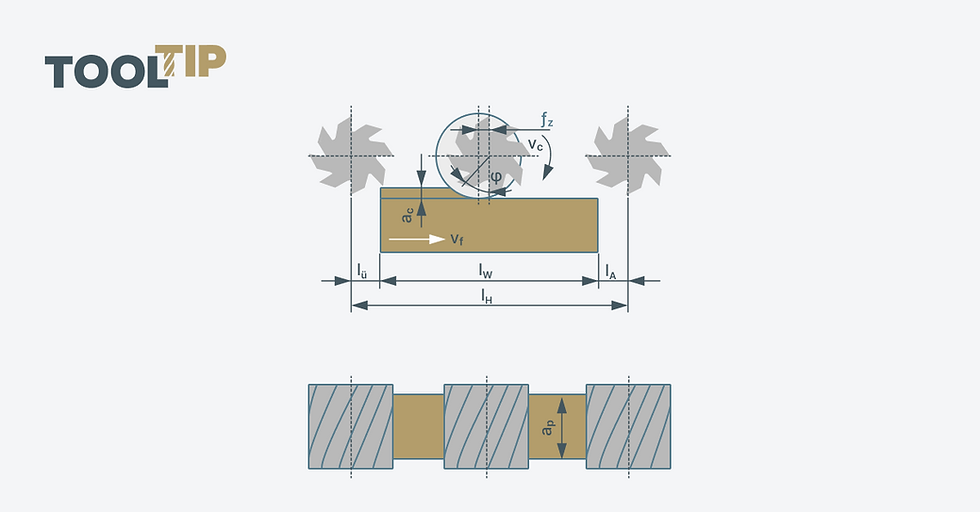
The feed per tooth indicates how far the workpiece or milling tool is moved forward per tooth and is specified in millimeters per tooth. The number of teeth on the milling tool indicates how many cutting edges the tool has. By calculating the feed per revolution, you can determine the effective feed value used for programming and setting the milling machine. Figures 2 and 3 compare the engagement conditions for circumferential and face milling, respectively.

When milling, the tool can perform various movements. The main movements are the cutting movement (main feed) in the longitudinal direction of the workpiece, the transverse movement (side feed) perpendicular to the longitudinal direction and the vertical movement (depth feed) to adjust the cutting depth.

Milling can be carried out in two different directions of feed movement: conventional milling and climb milling. They each have their own advantages and disadvantages. During counter-milling, the workpiece moves against the feed direction of the milling tool. This feed direction is often used on conventional milling machines. During synchronous milling, the workpiece moves in the direction of the feed direction of the milling tool. This means that the milling tool pushes the material towards the workpiece. This feed direction is often used on CNC milling machines.
Advantages of up-milling:
Lower load on the milling tool because the chip is initially pushed away from the cutting edge.
Less heat generation because the tool is not "pulled" directly through the material. will.
Better surface quality with not completely sharp cutting edges.
Disadvantages of up-milling:
Increased risk of vibrations and shrinkage as the milling tool "presses" on the material.
Possible formation of burrs on the workpiece edge.
Higher requirements for machine rigidity and stability.
Advantages of down-milling:
Lower risk of vibrations as the milling tool cuts the material in a controlled manner and guides it forward.
Better surface quality and higher accuracy because the milling tool "pulls" directly through the material.
Less burr formation on the workpiece edge.
Disadvantages of down-milling:
Increased load on the milling tool as the material is pressed directly onto the cutting edge.
Increased heat development, especially with materials that are difficult to machine.
Potentially higher wear on the milling tool.
The choice between up-milling and down-milling depends on various factors, such as the type of workpiece, the desired surface finish, the stability of the machine and the workpiece, and the tool manufacturer's recommendations. It is important to select the appropriate feed direction according to the specific machining task to achieve optimal results in terms of surface finish, tool life and machining efficiency.
Milling is used for a variety of applications such as creating flat surfaces, grooves, pockets, contours, threads, gear profiles, and complex three-dimensional shapes. It can be used in various industrial sectors such as metalworking, woodworking, plastic processing and precision component manufacturing. Depending on the specific requirements of the machining task, different milling processes are used (Figure 4).

Face milling: Face milling involves moving the tool perpendicular to the surface of the workpiece to create a flat surface or machine an edge. This process is often used for face machining of workpiece ends.
Circumferential milling: Circumferential milling is a milling process in which the milling tool rotates around its own axis and is guided along the circumference of the workpiece. It is also called peripheral milling or circular milling. Circumferential milling involves removing material along the circumference of the workpiece to create a desired shape, groove, recess or contour.
Hobbing: Hobbing is a special milling process in which a milling tool with special tooth profiles, called hobs or hob pins, is used to produce gears or other gear-like profiles. It is a process mainly used for the production of gears in the transmission and mechanical engineering industries.
Profile milling: During profile milling, the tool is moved along a specific contour in order to mill a specific profile into the workpiece. This process is used to create complex shapes or contours, such as gears, cams or free-form surfaces.
Circumferential end milling: Circumferential end milling is a process in machining technology in which the material is cut from both the end face and along the tool perimeter is removed.
Thread milling: Thread milling uses a special thread milling cutter to mill threads into the workpiece. This process enables the precise production of threads with high accuracy.
Сontour or shape milling: In contour or shape milling the tool is guided along a desired contour or shape to create complex shapes. It is often used for the production of 3D shapes or complex components.
These milling processes can be performed either on conventional milling machines or on computer-controlled milling machines (CNC mills), allowing precise control of the movements of the tool. The choice of the suitable milling process depends on factors such as the desired geometry, surface quality, material type and processing speed.


